Theory of Operation
Magneto telephones were the first widespread type of instrument. They derive their name from the
use of a magneto (small hand generator) to develop an alternating current of
about 100 Volts to signal the other party or operator. The advantages of magneto
circuits are simplicity, ruggedness, and ability to operate over
long and poor-quality lines. The disadvantages are the requirement of separate
batteries at each location (hence the use of the term "local battery" to
describe magneto instruments) and inefficient switchboard use.
|
Figure 1: The basic WALL PHONE diagram of a Magneto Circuit
|
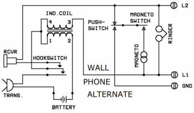 Figure 2: Alternate
magneto wall telephone circuit
Figure 2: Alternate
magneto wall telephone circuit
(redrawn from Northern Electric diagram).
Note the addition of the pushbutton, which permits the
user to ring either the switchboard or other parties.
|
| Candlestick and cradle instrument circuits.
The basic
circuit shown in Figures 1 and 2 is used in wall-mounted magneto phones having a separate
transmitter and receiver. Later types used a candlestick instrument with a separate
wall-mounted ringer box, and still more "modern" types used a cradle phone with
separate ringer box. The circuit for the former is shown in Figure 3 and for the
latter in Figure 4. Theory of 3 operation is identical for each, the major
difference being in the hookswitch
configuration. |
|
Figure 3: Candlestick circuit; use with
wall-mounted ringer
box above.
|
|
Figure 4: Cradle circuit; use with
wall-mounted ringer box above.
|
|
There are three parts to a
Magneto Circuit
The
Talking Circuit; The Receiving Circuit; and The Signalling Circuit.
Talking Circuit
The talking
circuit consists of the transmitter (microphone), the hookswitch, the primary of the induction coil (transformer), and the
battery. The transmitter is a carbon
microphone, composed of loosely packed carbon granules affixed to a metal (later a fiber or impregnated cloth)
diaphragm. The diaphragm vibrates in response
to the sound waves from the speaker’s voice, alternately
compressing and releasing the carbon granules, thereby varying their resistance. The varying current produced, flowing
through the primary of the induction coil,
induces a current into the secondary, which is carried by the line (connected to L1 and L2) to the
receiver of the distant party. The purpose of
the hookswitch is to interrupt the battery current when the instrument is not in use, extending the life of the
battery.
|
Receiving
Circuit
The receiving
circuit consists of the receiver (earphone), secondary of the induction coil, hookswitch, and external line. The
receiver is a diaphragm of magnetic material,
separated by a small distance from the permanent magnet
which is also the core of a winding of fine-gauge wire. Alternating current reaching the receiver from the external line,
through the induction coil and hookswitch,
varies the magnetic field produced by the permanent magnet core, setting the diaphragm in motion to reproduce
the sound waves impinging on the transmitter
diaphragm of the distant telephone. The purpose
of the hookswitch in the receiver circuit is to remove the phone from the line when not in use. Were this not done,
energy would be absorbed by the transmitter and
receiver circuits, diminishing the power received
by other instruments on the line, and interfering with the ringing signals.
Signalling
Circuit
The signalling circuit consists of two parts: the
magneto and the ringer. When cranked the
magneto generates 80 to 100 Volts a.c., at about 20 Hertz (cycles per second). It also contains a switch which
disconnects the magneto from the circuit when
not being cranked (possibly thereby connecting the
ringer--see Figure 1b). The ringer is a bell
resonating at 20 Hertz with a high impedance at voice
frequencies to prevent loss of talking power. There
are several possible configurations of the signalling circuit. One method (solid lines in Figure 1a) shows the ringer
connected across the two line wires, and the
magneto connected from L1 to
ground. The distant instrument in such a system
(or the switchboard) would use the configuration shown
by the dashed lines. In this way one party rings the other across the line wires, and the other rings the first from L1 to ground. Thus neither rings his own bell. An alternative
is shown in Figure 1b. Here the magneto switch disconnects the bell when the magneto is cranked. The solid lines thus
are identical to the circuit shown in Figure
1a. However, if the movable magneto wire is
transferred from ground to L2, the system is adapted to a multi-party line (i.e. one without switchboard). Any party can ring all other
parties, while not ringing his own bell. Each
instrument is then wired identically.
|
Rebuilding and Troubleshooting
Magneto instruments may be checked out and
improved for operation on magneto lines as follows.
Talking circuit: Old-style carbon granule
transmitters can still be used, but verify that they are not open;
resistance should measure between 50 and 300 ohms. However, more
clarity can be obtained by replacing old-style transmitters with new
"capsule" units used in modern telephones. Either F-1 units (2-1/4
inches in diameter) or T-1 units (1-3/4 inches) may be used, depending
on space. Electret units, providing even greater clarity, are packaged
in T-1 form and sold by Walker Equipment and others for G-style
handsets. The even smaller N-1 units, only 1-1/4 inches in diameter,
are sold by Roanwell as Model 200 for use in Model 52 operator sets.
Leads should not be soldered to their terminals due to the risk of heat
damage; instead utilize electrically conductive epoxy. European-style
desk and wall phones with "French" handsets have less internal
space for the transmitter, which may be replaced if necessary with the
above-mentioned N-1 unit. Care should be exercised in removing the
front cap of such transmitters: in certain units the carbon granules
are loose and will spill out if the handset is not held with the
transmitter opening upward during disassembly. The induction coil
should also be checked for continuity if the phone is not working. The
primary should measure between one and four ohms and the secondary
between 10 and 40 ohms. Defective cords are a common source of trouble
on old phones. Resistance of each wire should be no more than five ohms
and should not vary when the cord is flexed.
Receiving circuit: Common difficulties are
accumulation of dirt between the diaphragm and magnet faces on
long-pole receivers; too little or too much gap; loss of magnetism; or
open coils. Units can be checked by temporarily substituting a receiver
from a modern instrument; if there is a substantial difference in
volume, a new receiver can be purchased. Remember in replacing or
remounting cords to anchor the cord in such a way as to provide a
strain relief. Low-volume capsule or non-capsule receivers in handset
instruments can usually be replaced by an HC-3 capsule receiver, only
1-9/16 inches in diameter. (See rear of this booklet for suggested
suppliers of these parts.)
Signalling circuit: Bells can be checked for
continuity--coil resistance should measure a few hundred to a thousand
ohms. A common difficulty is accumulation of dirt or magnetic filings
between the magnet cores and the armature which moves the clapper.
Magnetos should produce between 80 and 100 V. Failure may be due to an
internal open circuit or simply to dirty or improperly gapped contacts
on the switch which connects the magneto when cranked.
|