|
Theory of Operation
Common battery systems permit more
efficient switchboard use because the Central Office can detect
automatically whether an instrument is
off the hook. This is indicated by a complete direct current path
through the
transmitter circuit, and so there is no need to "ring off" as on
magneto systems. In addition, transmission quality is higher because an
assured talking
current is provided all instruments from the Central Office. The price,
however, is the need for a better quality line and more complex
switching equipment. There are two types of common-battery circuits:
sidetone and
antisidetone. Sidetone is the sound in the receiver of the speaker’s
own voice, which can interfere with communication if the speaker is in
a noisy
location. Anti-sidetone circuits, introduced later, reduce the
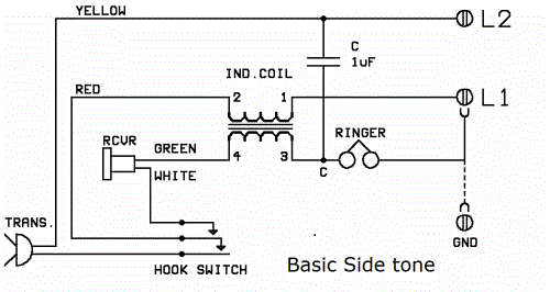
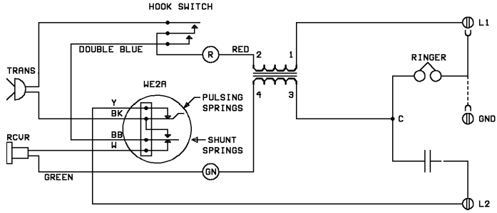
sidetone. The basic sidetone circuit (drawn from WE wall phone ["hotel phone"]) is shown in
Figure
right --->
|
|
Talking
circuit When the hookswitch is closed, the first contact to make
completes a circuit from L2 through the transmitter and induction coil
primary back to L1
and the Central Office. The low d.c. resistance of the instrument (200
to 300 ohms) operates a relay in the Central Office, flashing a light
on the switchboard. Talking power is provided from the same
source. Receiving circuit The last contact to make on the
hookswitch completes the receiver
circuit through the transmitter, capacitor (condenser in earlier
terminology), and secondary of the induction coil. Voice current from
the distant
party induces a current in the secondary which is heard in the
receiver. The
capacitor prevents direct current from passing through the receiver,
which might weaken its permanent magnet. Signalling circuit As with the
magneto system, ringing may be either bridged (from L1 to L2) or
divided (from one line to ground). In the bridged circuit, used on
private lines, the solid ringer connection in the schematic diagrams is
used.
In the divided circuit, used on party lines, employ the wiring shown in
the dashed connections. The capacitor performs double duty by also
preventingline current from flowing through the ringer, giving the
Central Office a false indication of off-hook condition. If ringing is
not desired, simply disconnect the two ringer leads and tape.
Candlestick and Cradle
instrument circuits
Figures illustrate different manufacturers’
basic circuits for the
candlestick or cradle phone instruments. Note that sidetone
circuits require only a three conductor cord from desk instrument to wall box.
Note also that all
common battery instruments require an induction coil (either in the
phone or on the wall). Simply wiring transmitter and receiver in series
will destroy the
receiver magnets in
time.
|
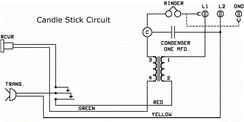
Common battery candlestick circuit with
separate ringer box
(drawn from 1926 Kellogg desk set)
|
Common battery candlestick circuit (drawn
from early WE desk set)
|

Masterphone Common Battery Cradle Circuit
|
Circuit of WE
634A ringer box with 46B induction coil;
for use with the Candlestick or Cradle phones.
This is a sidetone ringer circuit.
|
Anti-Sidetone Circuits
Two Western
Electric anti-sidetone circuits are described below.
The major differences from the sidetone circuits
are:
1. an additional winding in the induction
coil, which provides an induced voltage counter
to that set up by the local transmitter,
cancelling out
part of the sidetone;
2. a different
hookswitch arrangement; 3. an
additional capacitor; 4. a
four-conductor cord.
|
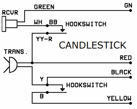
WE manual
anti-sidetone candlestick circuit
|
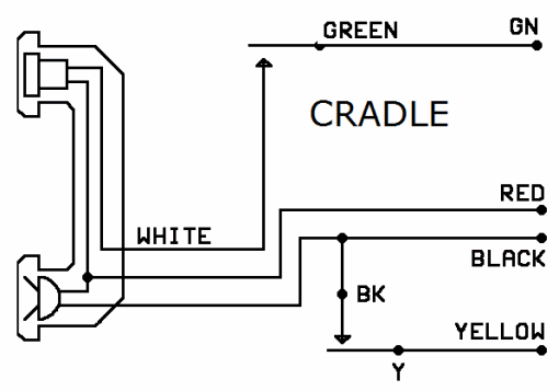
WE manual
anti-sidetone cradle circuit
|
|
Western
Electric anti-sidetone induction coils are numbered 146B and 101B. Other manuacturers’ units may be checked to determine
whether they contain the additional winding by
measuring the resistance between the
1-2 and 3-4 (L1-R and C-GN) windings. If open, it is a sidetone coil; if a
low
resistance (indicating the additional winding)
it is an anti-sidetone coil.
It should be noted that ringer boxes containing an anti-sidetone
induction coil can be used only with
candlestick and cradle instruments having a four-conductor
line cord and two separate parts to the hookswitch.
On the other hand, ringer boxes with sidetone induction
coils may be used with anti-sidetone-wired candlesticks and
cradle instruments by omitting the black cord
connection at the ringer box and
wiring as a sidetone unit. Otherwise any
manufacturer’s ringer boxes and
instruments may be intermixed so long as the
components conform to the circuits
shown.
<- WE 634A
ringer box with 146B or 101B antisidetone coil
(use with hand set circuits above )
|
COMMON BATTERY;
DIAL TELEPHONES
Theory of Operation
Addition of a dial to
a common battery manual instrument permits
automatic operation
of Central Office equipment. The dial consists of two sets of springs (metal leaf contacts):
1. pulsing springs:
these interrupt the complete d.c. path through the instrument a number of times
corresponding to the digit dialed (10
times for "0" in the
United States and in most other countries);
2. shunting springs:
these short out the rest of the instrument while pulsing in order to provide squarer pulses
to the dial equipment
and in order to
prevent unpleasant clicks in the receiver.
(Western Electric
dials open the receiver circuit instead of shunting it.)
WE 553A wall
telephone ("hotel phone")
|
|
Restoration and Troubleshooting
Several difficulties
commonly occur with aged dials. Patience and ingenuity are essential in
repair.
.....1. Bent
finger wheel, striking fingerstop or frame: remove and
straighten.
.....2. Dust and corrosion: remove with alcohol
and pipe cleaners or cotton
swab. The governor is particularly sensitive to the slightest ..........amount of dirt. Lightly oil metal
parts (except governor).
.....3. Loss of spring tension on finger wheel
shaft: this is provided by a
coil spring wound around the shaft itself in the center of the dial. The
..........
problem is rectified by adding one or a few turns to the spring. On WE
dials this is done from the front, removing the fingerwheel, ..........
number plate, and finally the plate
which stops the finger wheel shaft from rotating more than one turn.
With this latter removed, the .......... shaft can be rotated to provide additional tension. On
AE dials tension is increased from the rear by removing the end of the
coil ..........
spring
from the slit in the
shaft, twisting, and reinserting. In any case, take care not to release
the coil spring and be certain to clear .......... any impediments to free movement before increasing spring
tension.
.....
4. Misadjusted contact springs: this may occur from loss of fiber or
rubber pushers (which must be replaced or refabricated) or loss of ..........
tension
(which must be added by bending springs carefully).
Pulsing springs: observe operation while finger wheel is rotated: they
should open and close a number of times corresponding to the number
pulled, ending closed.
Shunting springs: they should shift just as the dial is rotated, and
remain operated for the entire time the pulsing springs pulse. They
should return to their normal position just as the finger wheel returns
to rest.
Conversion of Manual to Dial
Manual instruments having a dial blank may
easily be converted to dial operation by adding a dial, using the
appropriate circuit shown on the
preceding pages,
depending on the hookswitch configuration, whether handset or separate transmitter and
receiver, and whether sidetone or
anti-sidetone. Instruments
without physical provision for a dial may also be converted to dial use, by mounting the dial
on an appropriate home-made adapter.
Alternatively if one
does not wish to alter the original condition of an old
telephone, the dial
can be mounted separately in a wood or metal case, and
connected to the
instrument by a four-conductor line cord. "Pinging" of the bell when dialing can be
overcome by reversing the bell leads, or by increasing the spring tension
on the clapper.
|

