|
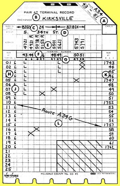 |
| .....Development
of this record was to aid the assignment clerk to assign facility pairs
without the use of schematics. all information is taken off the cable drawings
and placed on the card by an engineer. The record card can also display
cross connecting information.
.....This record is as flexible as each pyhsical cable pair is able to be spliced. At the same time it supplies all possible information which the service man can possibly need. An engineer can restrict pairs to appear only at terminals designed for their use while they may still appear at many other locations along the route from the central office. .....Distribution cables are designed so as to dedicate a single pair for one party service from the subscribers address to the central office or to a cross connect point. Cross connect points are being stressed because the Express cables must be filled to the last pair, due to large investments. Cross connect points may furnish facilities for distribution cables by access to all spare pairs or by connections to individual station carrier channels. Distribution cables, some of which may be express cables in the future, must be engineered to always have spare pairs along its route. .....In the distribution cable it must be possible for the combination man to pull a needed pair, (cut it and attach the drop) while identifying this pair without a mistake. It is possible to add additional MDF (split counts) to a distribution cable so as not to perform costly cable throws and still not make identification too difficult. .....This card can be overlayed onto the MDF record to display how each distribution pair is or is not used. Three cards
are displayed herein to describe their function.
|
|
|
| Pair is cut and used from the left. | |
| Pair is cut and used from the right. | |
| Pair is cut and used from both directions. | |
| Station Carrier connections, channels 3 and 7. | |
| Pair is Loaded at this location | |
| Pair has Build Out coil at this location | |
| Pair is Repeatered at this location |
| .....Only
those terminals which have a cable larger than one pair are shown on these
type of records. Where a short piece of small count cable is used to extend
services across a road, do not consider it as a distribution cable or place
the cable on the cable records. A pair can be traced this short distance
and the maintenance person can use the pairs as desired.
Go To: Contents |